Hardware
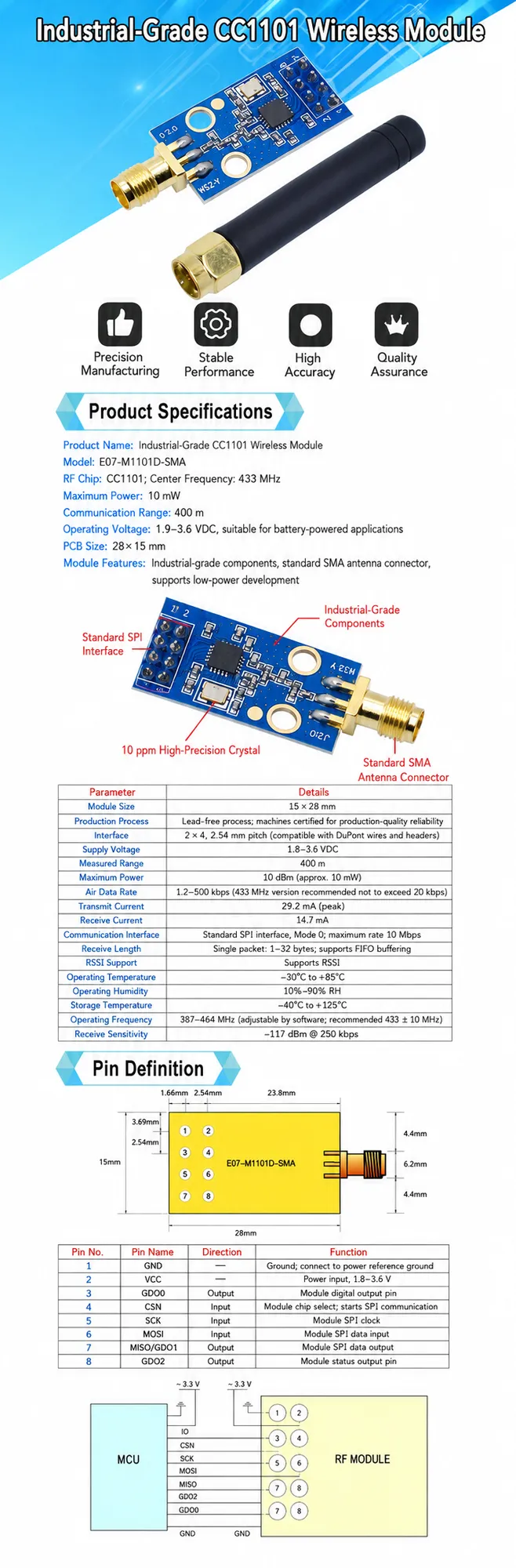
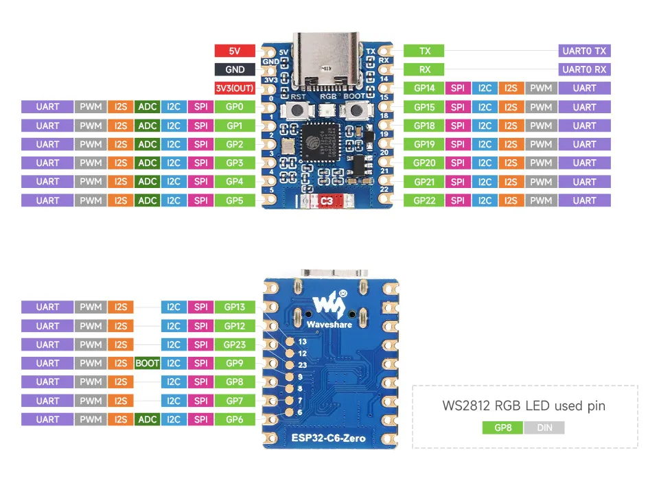
Waveshare ESP32-C6-Zero (native USB-C) wired to an E07-M1101D (CC1101, 433 MHz) radio. The E07 runs at 3.3 V — never 5 V. Attach a 433 MHz antenna to the E07.
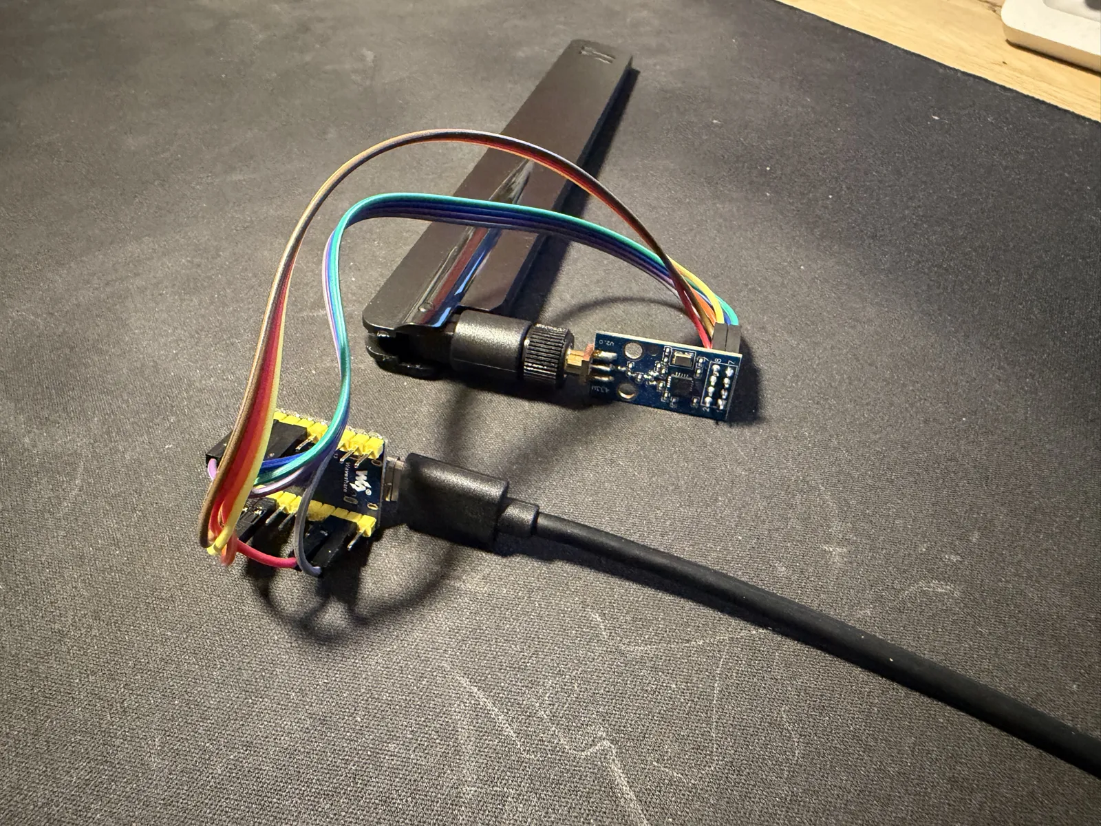
| E07 pin | Signal | ESP32-C6-Zero |
|---|---|---|
| 1 · GND | Ground | GND |
| 2 · VCC | 3.3 V power | 3V3(OUT) |
| 3 · GDO0 | TX data out | GP22 |
| 4 · CSN | SPI chip select | GP21 |
| 5 · SCK | SPI clock | GP19 |
| 6 · MOSI | SPI data in | GP4 |
| 7 · MISO/GDO1 | SPI data out | GP20 |
| 8 · GDO2 | RX data out | GP5 |
Both GDO lines are wired: GDO0 (GP22) transmits and GDO2 (GP5) receives — receive is what lets the board hear your existing remotes for discovery and keep rolling codes in sync. GP4/GP5 are the external-JTAG pins, free here because the console runs over the internal USB-Serial-JTAG.
Default carrier 433.42 MHz — a single device-wide radio setting,
tunable from the setup page. A real crystal drifts, so sweep 433.36–433.44 if a
motor stays silent.
Status LED
The C6-Zero's on-board RGB LED (GP8) shows onboarding progress and any later fault; the first matching row wins.
| LED | Meaning |
|---|---|
| Solid white | Radio off — CC1101 not detected at boot |
| Solid red | Not paired, commissioning window closed |
| Blinking blue | Commissioning window open, waiting for a controller |
| Blinking violet | On the Thread network, no Matter fabric yet |
| Blinking yellow | Paired with Matter, not on the Thread network |
| Solid green | Paired and on Thread — off after 5 minutes, back on any fault |
Reference: E07-M1101D-SMA manufacturer datasheet (pin definition and MCU wiring).